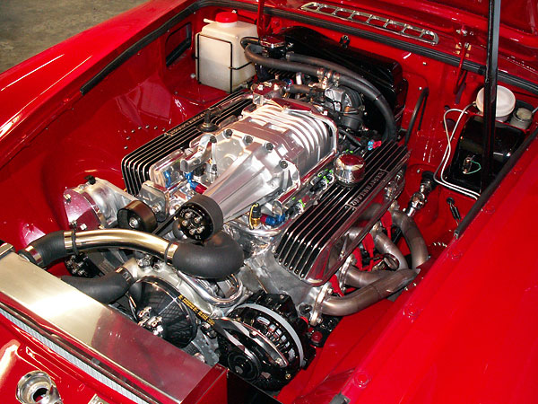
Under-Hood Eaton M90 Supercharger (on an MGB w/ Buick 215 V8)
as published in British V8 Newsletter, Volume XV Issue 2, September 2007
by: Bill Jacobson
Here are some construction photos of my new supercharger installation. The
intake manifold, M90 supercharger, and drive system all fit under a stock
MGB hood (although my hood had already been modified for air cleaner
clearance.) This installation includes MegaSquirt electronic fuel injection
and a Ford EDIS ("Electronic Distributorless Ignition System"). It also features
cowl/cold-air induction. The original Smith's heater housing has been modified,
and now functions as an air filter housing for the engine.
Fabricated Intake Manifold
The intake manifold pieces were hand-formed, mostly from 1/4" T6061 aluminum. I have a spare engine block and heads that I bolted together to form a jig. The plenum bottom and the side plates that mate to the cylinder heads were constructed first, and I built up from there. Basically I made a few pieces, jigged them up in position (on the block/heads), and took the whole works down to the machine shop.
All the TIG welding was done by a local fabrication shop called "Peterzelka Brothers". After each bit of welding, I brought the manifold back home, made some more parts, jigged them up, and took them back for more TIG welding. Finally, the top and sides were machined true on a large milling machine.
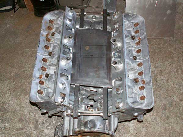
The plenum bottom and the side plates that mate to the heads were constructed first.
The box-tube structure shown here was just for temporary locating/clamping.
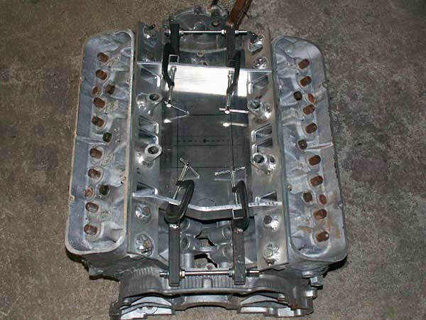
Beginning to build-up the plenum area...
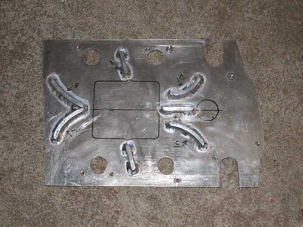
The "top" of the intake manifold, shown upside-down to display vanes...
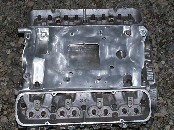
The fabricated intake manifold, finished except for some polishing...
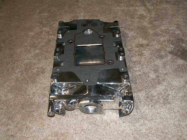
With the gasket in place, you can better see how the supercharger mates up.
This view also shows the thermostat / water neck boss.
Modified Blower Housing
Since the blower was made for a 3800 V6, the blower housing had to be trimmed slightly to match the Buick 215 V8 port spacing and to allow room for the Delphi fuel injectors. Fortunately, the blower housing casting is very thick in this area, which allowed room for the modifications. The inlet angle was reduced on a milling machine. Then I made an angled spacer plate that points straight backward for hook-up to the cowl-induction system.
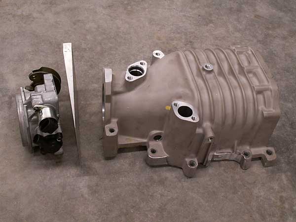
Compact throttle body with integrally mounted throttle position sensor (TPS) and idle bypass valve.
This view also shows the angled spacer plate that points toward the cowl-induction system.
Notice that the supercharger housing was modified slightly for fuel-injector clearance.
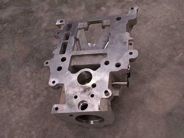
1996 Buick 3800 V6 supercharger housing (GM/Eaton M90), modified slightly to fit on a Buick 215 V8.
Custom Blower Drive System
Because I wanted to keep things compact (for a clean look), the blower drive
system was a real head-scratcher! The oil pump, water pump, and hood all seemed
to cause clearance problems. Also, there are a limited number of 8-rib serpentive
belt lengths available to work with.
I started out making one piece at a time, using cardboard templates to save
time and aluminum. Most of the belt drive system's frame is made from 1/2"
aluminum plate. I used a metal lathe to make the idler bearing housing. The
sealed bearings are press-fit with snap rings to make sure they stay put.
The smaller black pulleys were made by ZZ Performance. The primary drive belt
tensioner is from a Dodge truck, and the secondary drive belt tensioner is
from a Ford. I made a round mounting bracket to house the primary tensioner.
This allowed the tensioner to be reverse-mounted for additional clearance
at the oil and water pumps.
|
Enjoying this article? Our magazine is funded through the generous support of readers like you! To contribute to our operating budget, please click here and follow the instructions. (Suggested contribution is twenty bucks per year. Feel free to give more!) |
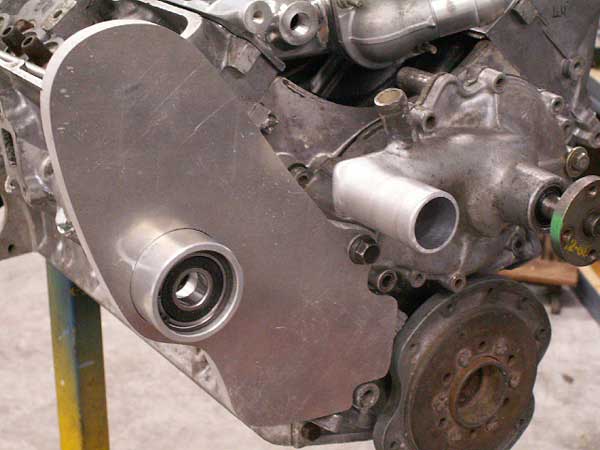
Blower drive system: lathe-turned idler bearing housing.
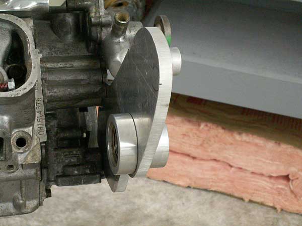
The water pump inlet had to be cut-off and rebuilt with a ninety-degree elbow.
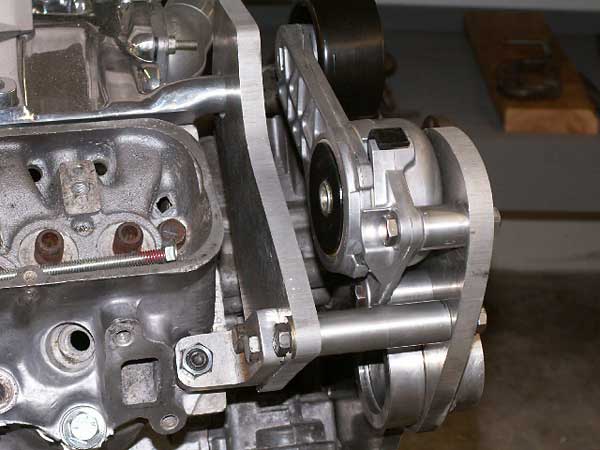
The Ford secondary drive belt tensioner ("idler pulley") in place.
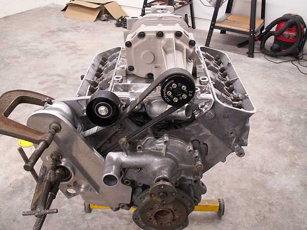
The thermostat water neck is has been extended to provide belt/pulley clearance.
Less obviously, the distributor has been displaced. Actually, an old distributor has
been cut-down to serve as an oil pump drive. (Buick 215 engines had cam-driven oil
pumps.) A Ford EDIS ignition system makes the distributor obsolete.
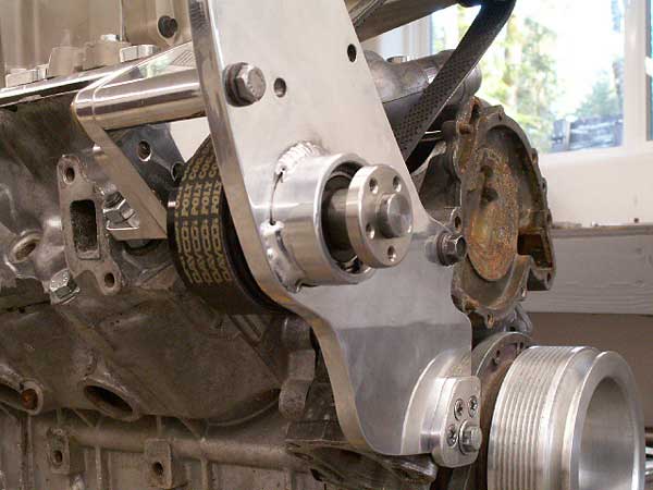
These mounting flanges allow use of a variety of "bolt-on" ZZ Performance pulleys for drive ratio changes, if desired.
EFI Fuel Rail
Here are some pictures of the fuel rails, main pressure regulator, and remote fuel cell.
In order to improve low speed driveability, I recently installed a Vortech Fuel
Management Unit (FMU). An FMU is a secondary fuel regulator that installs in series
with the main regulator on the return line to the tank. The FMU is triggered by a
pneumatic signal from the supercharger. I selected an 8:1 ratio unit. In other words,
my FMU increases fuel pressure 8 pounds per square inch for every 1 pound of
boost. (The FMU can be re-calibrated for 3:1 through 12:1 ratios.)
Why is an FMU desireable? In my case, the 21lb injectors are correctly sized for
engine demand under full boost. However they're a little large for idle or low
speeds, causing very short duration fuel pulse's at low load conditions. The FMU
allows me to adjust fuel pressure lower (to 28-30 lbs at idle) and still have high
fuel pressure under boost. The lower fuel pressure at idle or low engine loads
allows longer fuel pulses for improved low speed driveability and fuel mileage!
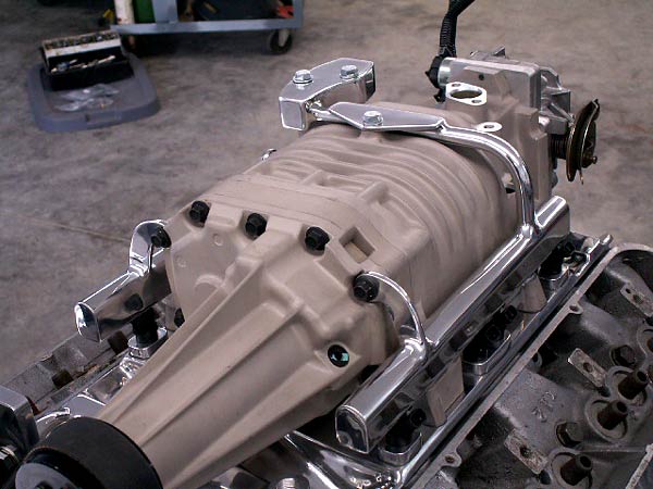
Ross Machine Racing extruded aluminum fuel rail stock was used to plumb fuel to the injectors.
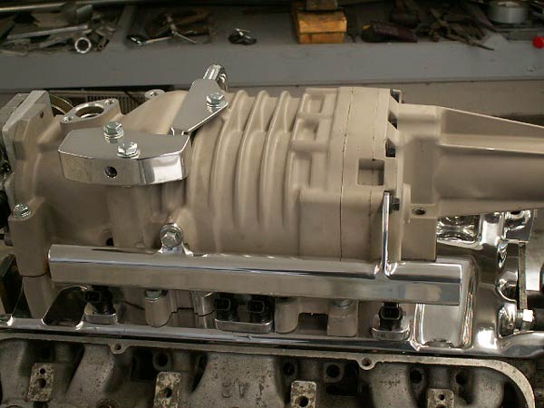
The fuel injectors are 21lb Delphi II units, nominally from a 4.8-5.3L GM pickup truck.
I selected the Delphi units for their relatively small external size, which allowed them
to fit neatly alongside the blower housing.
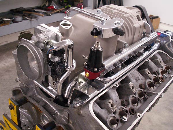
The main fuel pressure regulator is an Aeromotive unit that is adjustable and boost referencing.
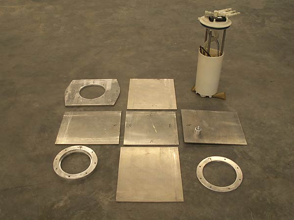
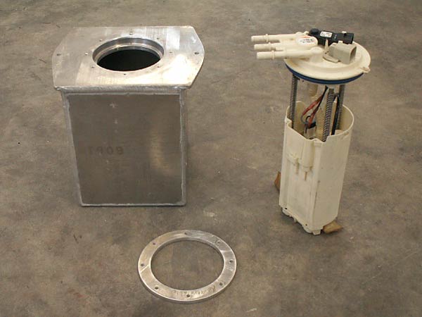
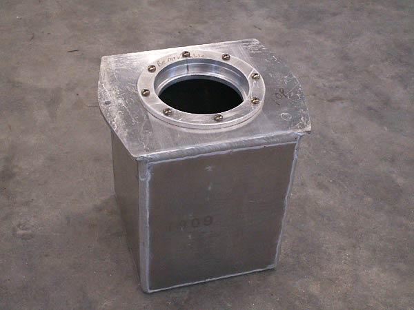
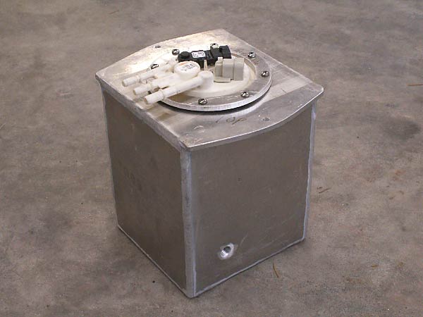
Fabricated Auxiliary Fuel Tank
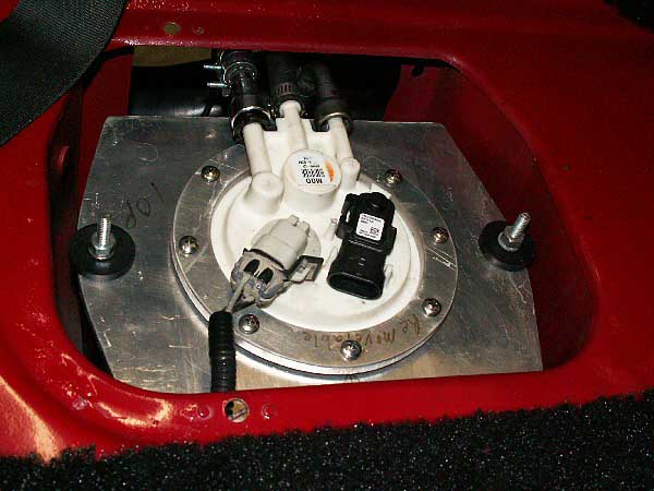
The auxiliary fuel cell contains a slightly-shortened, late-model Chevy Astro
high-pressure fuel pump that supplies the engine's requirements. Fuel is pumped
from the main tank to the auxiliary fuel cell by a 72 gph low pressure pump. Excess
fuel is cycled back from the fuel cell to the main tank via a return line. This keeps
the cell full at all times.
The auxiliary fuel cell is slightly larger then one of the MGBs original 6-volt batteries. I
designed it to is mount in the passenger-side battery compartment. (Editor's note: on
MGBs, there are two battery boxes suspended behind the driver and passenger seats
respectively.) A "Group 26" 12-volt battery is mounted in the driver-side location.
Ford EDIS (Electronic Distributorless Ignition System) Mechanical Parts
My Ford Electronic Distributorless Ignition System came off of a 1996 Crown Victoria
with a 4.6L V8.
EDIS is a type of capacitive discharge ignition which operates on the "wasted spark"
principle (which briefly means that it fires two cylinders at once, but only one of
the two sparks matters.) Base ignition timing is determined by a Hall Effect sensor
situated to detect the passing "teeth" on a crank mounted trigger wheel.
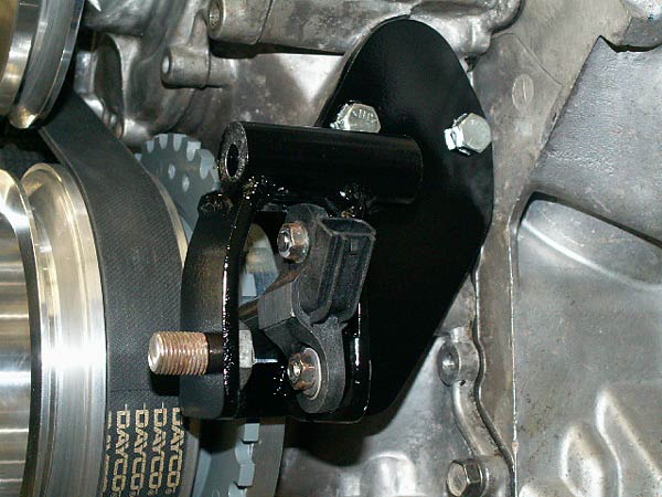
I selected an ignition pick-up coil from a parts catalog by looking for one with conveniently
oriented mounting tabs. The one I selected is nominally for a Ford Escort, although pretty much
any Ford pick-up coil could be made to work. (They all provide a similar signal.)
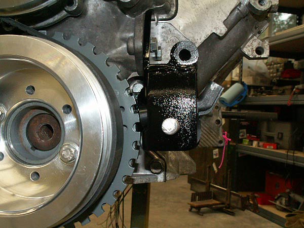
I ordered the trigger wheel from "www.triggerwheels.com". They offer trigger wheels in several
diameters. This one is a 7.25" unit that I machined down to 7.125" to clear the timing cover.
A also enlarged the center hole so it'd fit the back side of the Buick 215 harmonic balancer.
(There are 36 tooth positions on the trigger wheel, except one tooth is deliberatly missing so
the system can identify both the crank position angle and the engine speed very accurately.)
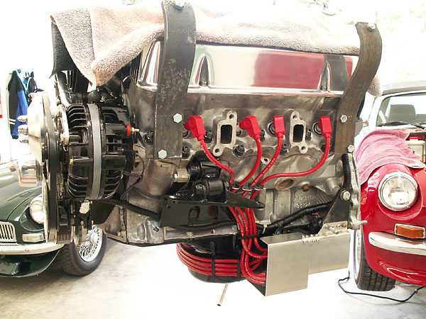
I made a mounting bracket for the primary coil packs, and mounted them to the side of the oil
pan. A layer of header wrap between the pan and coils shields them from heat. An aluminum
cover helps protect the coils from road debris. (Also, in this photo you can see a torque
arm set-up that attaches to the crossmember bolts and limits rotation of the engine.)
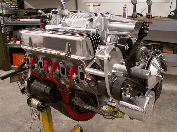
Aluminum billet pulleys for crankshaft and water pump were made to my specs by Peterzelka Brothers.

EDIS and MegaSquirt Electronic Controllers
The ignition's electronic control module is mounted to a "main electrical center"
plate, which is located inside the car on the passinger-side kick panel. The
MegaSquirt electronic fuel injection system controller, voltage regulator,
relays and an auxiliary fuse panel are also mounted to this plate.
There are only two short leads between the MegaSquirt controller and the EDIS
controller, but they're both very important. The fuel injection system gets engine
speed information from the ignition controller, and based on engine speed and other
factors it communicates required ignition timing advance back. Ignition advance
"curves" are stored in the MegaSquirt controller, not the ignition controller!
(Incidentally, I found them remarkably easy to tune.)
In Ford terminology, the signal wire from the EDIS module to the MegaSquirt system
is known as the "Profile Ignition Pickup" (PIP). You can think of it as an engine
speed or "tachometer" output. The MegaSquirt controller uses the PIP signal, the
Manifold Absolute Pressure (MAP) sensor signal (which, very much like vacuum, is an
indicator of engine load), and a user-programmed table to determine required
timing advance. The engine won't run if the PIP signal is lost. (For one thing, the
fuel injection system will assume the engine has stopped, and cease pumping gas.)
The second signal wire is used by the fuel injection system to communicate
required ignition advance back to the ignition controller. In Ford terminology, it's
known as the "Spark Angle Word" (SAW) wire. When the SAW wire is disconnected, the
ignition system reverts to base timing... almost analogous to disconnecting
a conventional distributor's vacuum advance hose. The base timing is determined by
the physical angle between the crank sensor and the missing tooth on the trigger
wheel. (I installed an inline fuse in the SAW wire to make it more convenient to
verify base timing with a timing light.) Nominally base timing for the EDIS system
is 10° before TDC.
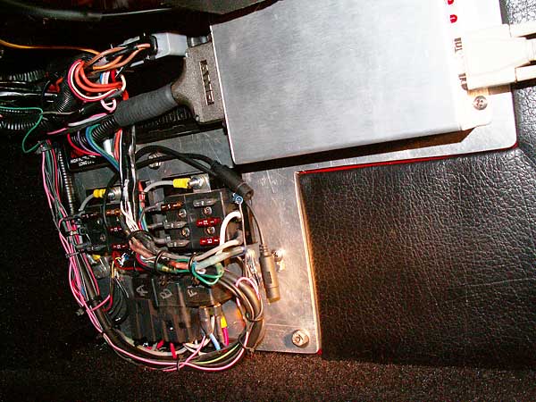
MegaSquirt is the large silver box on the right, and the EDIS module is just to the left of it.
The two black cables with plug-in connectors are for hooking-up an LC-1 wide-band oxygen sensor
controller to a laptop computer. O2 sensor data can also be viewed through the MegaSquirt screen.
The white cord (in the top right corner) is for connecting MegaSquirt to a laptop computer.
Normally a a carpeted panel covers this all up...
Air Filter Housing (For cowl-induction... made from an old Smith's heater box!)
The heater box was added onto above and below, to allow airflow around the the 8" diameter K&N filter.


The rubber coupling between the air box and throttle body was made from a plumbing roof seal!


Installation in the MGB
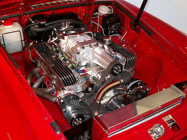
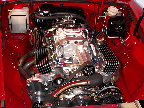
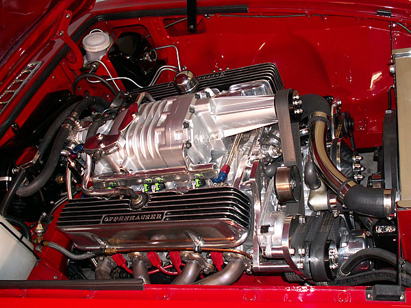
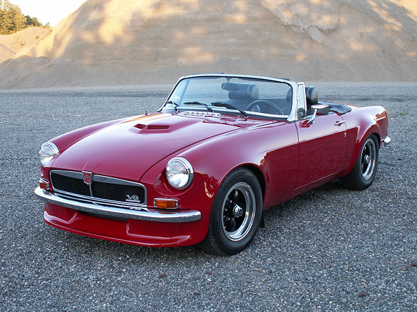
The new supercharger would fit under an unmodified hood. The GTO-style scoop came earlier...
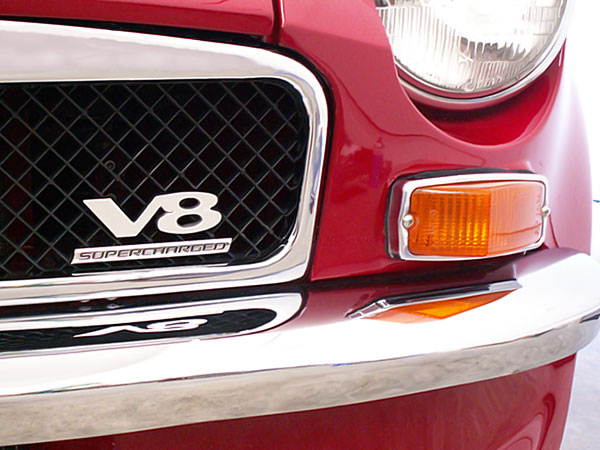
The finishing touch: a "Supercharged" badge from a Chevy Cobalt SS
Disclaimer: This page was researched and written by Bill Jacobson. Views expressed
are those of the author, and are provided without warrantee or guarantee. Apply at your
own risk.
Photos by Bill Jacobson for The British V8 Newsletter. All rights reserved.

