Keeping your Bearings
An introduction to oil accumulators and their installation.
as published in BritishV8 Magazine, Volume XVIII Issue 1, December 2010by: Bill Young
With the recent development of BritishRaceCar.com as a sister website to BritishV8, we're beginning to
see a few oil accumulator systems in detailed close-up photographs. These systems are popular on
road racing sportscars, but are also quite useful on the street because they can help extend the
life of the lower end bearings in your engine.
There are a couple of different types of systems in common use. The most basic oil accumulators are
gravity assisted. Their sealed tanks must be mounted vertically where oil can be stored and
returned to the engine when needed. A second and more versatile type of oil accumulator uses
pressurized air. These can be mounted in any orientation. Both type of systems are plumbed in a
similar manner, it's just the ability of the later piston type cylinders to be mounted in a variety
of positions that makes that system more versatile.
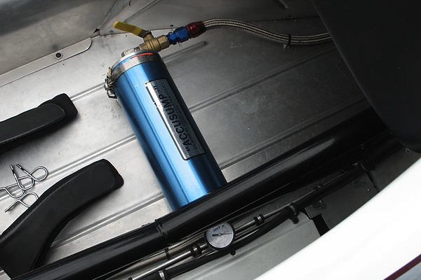
Piston type systems came into use in the early 1970s and were first patented in 1976. In the early
1980s Canton Racing Products acquired the patent rights from the original owner and set about making
modifications and improvements to the end caps and seals to improve strength, safety, and
serviceability. The brand name "Accusump" is now almost generic for this type of system.
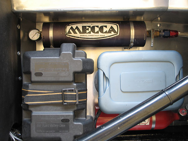
Accusump isn't the only name you'll find on oil accumulators when you visit the track or the
performance parts store. This older Mecca oil accumulator is used on Kent Prather's famous MGA.
Mecca was bought out by Canton Racing Products and Mecca's products were relabeled Accusump.
Moroso manufactures both gravity and piston type oil accumulators. Their piston-type products
vary slightly in design from Canton's, but the basic function and plumbing are the same.
How Oil Accumulators Work
The basic idea of these systems is to store a quantity of oil under pressure and to release
it to flow into the engine when the oil pressure drops below the internal pressure in
the accumulator. To prevent a loss of pressure when the engine is shut off, a valve (either
manual or electric) is installed in-line to block the flow at those times. When the valve
is opened and the engine is off, oil flows out of the accumulator and through the lines to
the engine. You don't want oil to flow back into the pump and pan so a one-way check valve
is installed to direct the pressurized oil into the engine oil galleries.
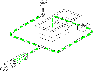
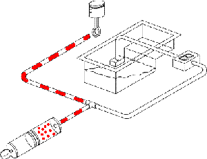
Charging and discharging schematic diagrams (courtesy of Canton Racing Products).
In recent years, oil accumulator systems have become popular as an aid to turbocharger cooldown.
The accumulator system releases oil into turbo bearings after engine shutdown. It's conceivable
for a turbo motor to actually run two separate accumulators, one for engine bearings and one for
the turbo. A turbo oiler would necessarily be plumbed differently and a shut-off valve wouldn't
be needed because the turbo's oil needs are after engine shut down.
Many, many race cars today run oil accumulators, which is one reason that you often hear a car
revving in the pits just prior to shut down after a track session. The driver is getting
the oil pressure up with the engine rpm and then closing the valve to the accumulator in
preparation for the next start cycle. An additional benefit of these systems is that while
the car is running on the track, if the engine begins to lose oil pressure due to a low level
in the sump (due for example to high cornering forces), the oil in the accumulator will flow
into the engine and protect the lower end until the oil pump can regain pressure and refill
the accumulator.
Most racers mount the accumulator in the driver's compartment and use a manual ball valve
to open and close the accumulator. Cable operated valves are sometimes used for installations
where the plumbing is out of reach. Electrically operated solenoid valves are popular with
some racers too, but they're best suited for street driven cars. They can either be wired into
a separate switch, or else through a relay actuated by the ignition switch. When actuated by
the ignition switch, a secondary manual "maintenance" switch should be mounted in the system
to prevent pressure loss when the ignition switch might be turned on for other reasons besides
starting the car.
Plumbing Installation
Perhaps the easiest way to install an accumulator system is to use a sandwich plate such
as used to plumb in a remote oil filter or oil cooler. Most of these systems are plumbed
in with 1/2" ID hose (-8 AN) just like most remote filters and oil coolers, so tapping
into such an existing system would be fairly easy. By contrast, finding a suitable
large oil port on most engines other than at the oil filter mounting is difficult.
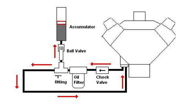
The basic installation is by using a "T" fitting in the pressure line and a one-way check
valve to prevent oil from flowing backward into the pump outlet. (Figure: Bill Young.)
Enjoying this article? Our magazine is funded through the generous support of readers like you!
To contribute to our operating budget, please click here and follow the instructions.
(Suggested contribution is twenty bucks per year. Feel free to give more!)
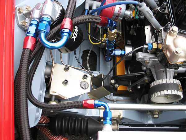
Here is a close-up photo of John McCue's MG Midget racecar
showing the T-fitting for the
oil accumulator as well as the check valve mounted just after the oil filter assembly.
The accumulator is mounted in the driver's compartment.
If you're not running a remote oil filter or oil cooler, then looping off a "sandwich plate"
with the T fitting and check valve would also be very effective. These are available from
a variety of sources like Trans Dapt, which manufactures all types of oil cooler and remote
filter mounts and accessories.
Example Installations
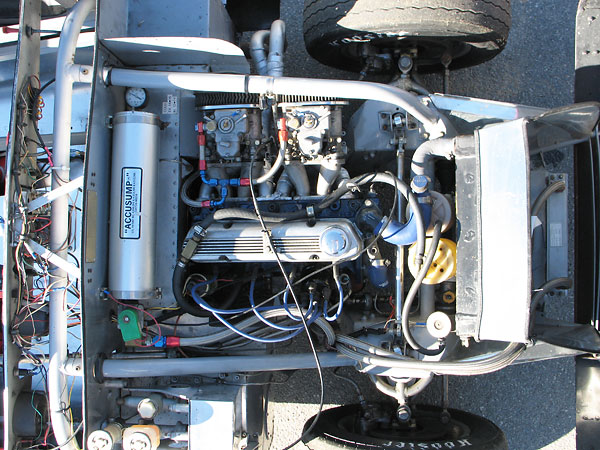
On Vic Schuster's Turner MkIII racecar,
the oil accumulator is mounted in the engine compartment and operated by an
electric solenoid valve. This would be the most common type of installation in a street-driven car.
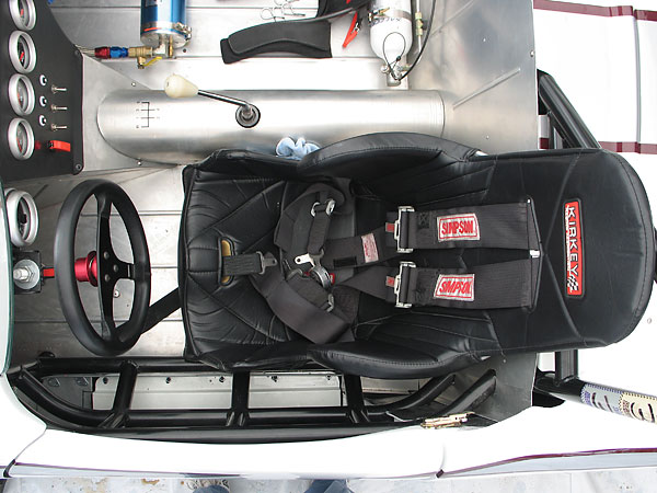
On Bill Thumel's Elva Courier racecar,
the oil accumulator is mounted in the cockpit and
operated by a manual valve on the tank. This is the most common installation on racecars.
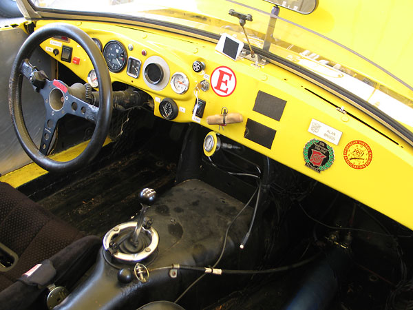
The B-Stingers' MGB racecar uses a cable operated valve. In this photo you can see the cable
just to the right of the shifter and fitted with a safety pin to prevent inadvertent operation.
Disclaimer: This page was researched and written by Bill Young. Views expressed
are those of the author, and are provided without warranty or guarantee. Apply at your
own risk.
Photographs by Curtis Jacobson for BritishRaceCar.com and BritishV8.org. All rights reserved.
BritishV8 wishes to gratefully acknowledge Canton Racing Products' kind permission to republish
their charging and discharging schematic diagrams (above).

